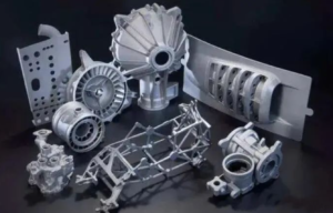
Hundreds of spare metal and plastic parts are designed and manufactured every day. Without acceptable standards to control product dimensions, designers and mechanics will go crazy because they will add a lot of difficult work. To simplify design and manufacturing for machinists, Tolerance International develops and publishes international tolerance standards that can be used for machining, cutting, and other parts. Generally, the common tolerance standard for mechanical drawing in CNC machining is ISO 2768. This article introduces ISO2768 in detail.
What is ISO 2768?
ISO 2768 is an international standard created by the International Organization for Standardization (ISO) to simplify drawing specifications for mechanical tolerances. Its creation and implementation facilitates design and manufacturing, not only helps determine standard machining tolerances, but also minimizes inconsistencies while considering manufacturing costs, allowing easier and closer cooperation between different companies. ISO2768 is divided into two parts, namely ISO-2768 1 and ISO 2768-2. General tolerances for linear and angular dimensions are given in Part 1. Part 2 provides geometric tolerances for features. ISO 2768 applies primarily to parts manufactured by machining or material removal. For part dimensions that are not marked with tolerances, this standard must be followed. Note that all tolerance limits are in millimeters.
Part 1: ISO 2768-1
ISO 2768-1 aims to simplify the representation of drawings and specifies general tolerances in four tolerance classes (f – fine, m – medium, c – coarse, v – very coarse). Increase. This applies to linear and angular dimensions such as external dimensions, internal dimensions, step length, diameter, radius, distance, external radius, chamfer height on broken edges.
Where the general tolerances of ISO 2768 apply, ISO 2768 should be followed by the tolerance class in or near the title block (eg ISO 2768-f / ISO2768-m ).
Below is the tolerance table for the four precision classes. You can choose the best one according to your processing ability and design requirements.
- Table 1 – Permissible deviations in linear dimensions (excluding damaged edges)
| Grade of Tolerance | GRADE | 0.5~3 | >3~6 | >6~30 | >30~120 | >120~400 | >400~1000 | >1000~2000 | >2000~4000 |
| f | Precision | ±0.05 | ±0.05 | ±0.1 | ±0.15 | ±0.3 | ±0.3 | ±0.5 | |
| m | Medium | ±0.1 | ±0.1 | ±0.2 | ±0.3 | ±0.5 | ±0.8 | ±1.2 | ±2 |
| c | Coarse | ±0.2 | ±0.3 | ±0.5 | ±0.8 | ±1.2 | ±2 | ±3 | ±4 |
| v | Very Coarse | ±0.5 | ±1 | ±1.5 | ±2.5 | ±4 | ±6 | ±8 |
- Table 2 – Allowable Deviations for Angular Dimensions
| Grade of Tolerance | GRADE | ≤10 | >10~50 | > 50~120 | >120~400 | > 400 |
| f | Precision | ±1˚ | ±0˚30´ | ±0˚20´ | ±0˚10´ | ±0˚5´ |
| m | Medium | ±1˚ | ±0˚30´ | ±0˚20´ | ±0˚10´ | ±0˚5´ |
| c | Coarse | ±1˚30´ | ±1˚ | ±0˚30´ | ±0˚15´ | ±0˚10´ |
| v | Very Coarse | ±3˚ | ±2˚ | ±1˚ | ±0˚30´ | ±0˚20´ |
- Table 3 – Permissible deviations in linear dimensions of damaged edges (rounding radius and chamfer height)
| Grade of Tolerance | GRADE | 0.5~3 | > 3~6 | > 6 |
| f | Precision | ±0.2 | ±0.5 | ±1 |
| m | Medium | ±0.2 | ±0.5 | ±1 |
| c | Coarse | ±0.4 | ±1 | ±2 |
| v | Very Coarse | ±0.4 | ±1 | ±2 |
Part 2:ISO2768-2
ISO 2768-2 aims to simplify drawing and correct general tolerances for three tolerance classes (H, K and L). This part covers general tolerance ranges for flatness and straightness, cylindricity and roundness. You can view the tolerance chart below.
- Table 4 – General tolerances for straightness and flatness
| Grade of Tolerance | ≤10 | >10~30 | >30~100 | >100~300 | >300~1000 | >1000~3000 |
| H | 0.02 | 0.06 | 0.1 | 0.2 | 0.3 | 0.4 |
| K | 0.05 | 0.1 | 0.2 | 0.4 | 0.6 | 0.8 |
| L | 0.1 | 0.2 | 0.4 | 0.8 | 1.2 | 1.6 |
- Table 5 – General Tolerances for Straightness
| Grade of Tolerance | ≤100 | >100~300 | >300~1000 | >1000~3000 |
| H | 0.2 | 0.3 | 0.4 | 0.5 |
| K | 0.4 | 0.6 | 0.8 | 1 |
| L | 0.6 | 1 | 1.5 | 2 |
- Table 6 – General tolerances for symmetry
| Grade of Tolerance | ≤100 | >100~300 | >300~1000 | >1000~3000 |
| H | 0.5 | 0.5 | 0.5 | 0.5 |
| K | 0.6 | 0.6 | 0.8 | 1 |
| L | 0.6 | 1 | 1.5 | 2 |
Table 7 – General tolerances for circular runout
| Tolerance class | Circumferential runout tolerance |
| H | 0.1 |
| K | 0.2 |
| L | 0.5 |


